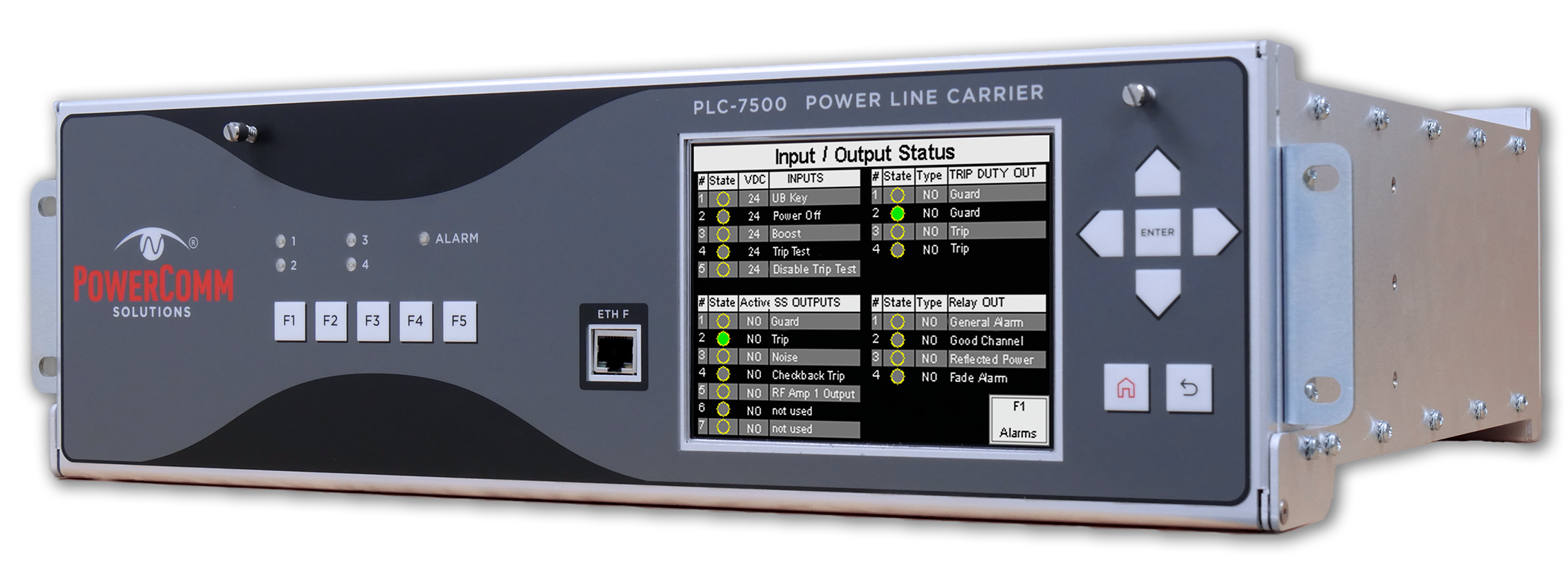
PLC-7500
Power Line Carrier Set
The PLC-7500 combines the standard functionality of legacy transmitter/receiver sets with a modern, diagnostics‑rich design. It delivers unmatched visibility into your PLC channel by capturing time‑stamped events, trending key parameters, and offering on‑demand spectral analysis, so you can commission faster, extend maintenance cycles, and troubleshoot with confidence.
SOE capacity
32,768 events
Trending
Spectral captures
On‑demand + event‑driven
DNP3 protocol
Included standard
Built‑In Legacy Functions, Modern Design
The PLC-7500 is a state-of-the-art Power Line Carrier set that combines all the standard functionality of legacy transmitters/receivers with a comprehensive set of enhanced features not available on any other carrier set. It supports ON/OFF and FSK applications and adds deep insight through real‑time and event‑driven measurements. Backed by 25 years of expertise in measuring, aligning, and monitoring power line carrier systems, the PLC‑7500 delivers the visibility utilities need, with one‑touch access to critical information on a large front‑panel display, without sacrificing simplicity.
Unmatched Event Visibility
Legacy devices typically store only 3,500 to 5,000 events before critical data is overwritten. The PLC‑7500 records up to 32,768 time‑stamped events with triggers on frequency, level, reflected power, impedance, and phase. Trend level, reflected power, impedance, and phase with programmable sampling intervals as often as hourly to establish baselines for system integrity analysis. Capture and compare "as‑left" snapshots to extend maintenance cycles and reduce unnecessary truck rolls.
In legacy units, Checkback tests only report pass or fail. The PLC‑7500 adds depth by recording level, reflected power, impedance, and phase during each Checkback event, providing a clear picture of on‑off carrier channel health without requiring an outage.
Advanced Diagnostics, Included Standard
The PLC‑7500 is the only Power Line Carrier set that reports reflected power not only as traditional percent, but also in its polar components of impedance and phase. Percent reflected power provides only a simple magnitude, with no directional context about what is happening on the communication path. By contrast, knowing both impedance and phase delivers a new level of diagnostic clarity, simplifying alignment during commissioning and providing critical insight into changes on the communication path during troubleshooting.
Event‑driven or real‑time spectral captures provide immediate visibility during commissioning and mis‑operation analysis, allowing quick identification of stray or unexpected signals that could affect critical protection channels. Event‑driven captures are stored and can be retrieved directly on the front panel display for later review.
| Transmitter / Receiver | |
|---|---|
| Frequency Range | 30 kHz to 600 kHz |
| Frequency Resolution | 10 Hz |
| Frequency Stability | ±1.5 Hz |
| Frequency Accuracy | ±2 ppm, Aging: 1 ppm per year |
| Frequency Temperature Stability | ±1.0 ppm |
| Modulation | ON/OFF or FSK |
| FSK Frequency Shifts | ±100, ±250, or ±500 Hz |
| Transmitter | |
| Output Impedance | 50 Ω or 75 Ω unbalanced (Load Impedance: +100% to −50%) |
| Output Power | 10 W max, 1 W min |
| Harmonic & Spurious Output | 55 dB below TX frequency at rated full power |
| Output Accuracy | ±1 dB Level, 1% SWR |
| Receiver | |
| 4‑Wire Receiver Input Impedance | > 600 Ω |
| Receiver Sensitivity (15 dB Margin) | 70.7 Vrms to 28.1 mVrms (50 dBm to −18.01 dBm) |
| Receiver Sensitivity (Absolute) | 70.7 Vrms to 5.0 mVrms (50 dBm to −33.01 dBm) |
| Min In‑Band SNR for Good Channel Operation | 13 dB for FSK, 20 dB for ON/OFF |
| Power Supply | |
| Input Voltage (Range) | 24 Vdc (18–36 Vdc), 48 Vdc (36–75 Vdc), 125 Vdc (100–200 Vdc), 250 Vdc (200–400 Vdc) |
| Power Requirements | 23 W (Power Amp OFF), 34 W (Power Amp 1 W), 63 W (Power Amp 10 W) |
| Redundancy | Optional (Amp / PS) |
| Inputs | |
| Type | 5 Optically Isolated |
| Voltages | Jumper configurable: 24, 48, 125, or 250 Vdc |
| Outputs & Alarms | |
| Relays | 7 Solid State 1 A; 4 Standard 1 A Form A/B Programmable; 4 Trip Duty 10 A Form A/B Programmable |
| Power Fail | 2 Standard 1 A, Form C |
| LEDs | 4 Programmable, 1 Alarm |
| IRIG‑B Timecode Input | |
| Connector | 1 Rear, BNC |
| Signal Type | Programmable: Modulated (10 Vpp max) or Unmodulated (5 V TTL) |
| Communication Ports | |
| Ethernet | 1 Front, 1 Rear, RJ‑45, 10BASE‑T / 100BASE‑TX |
| RS‑422/485 | 1 Rear, Terminal Block, 9600–115200 baud |
| RS‑232 | 1 Rear, 9‑Pin D‑sub, 9600–115200 baud |
| Environmental | |
| Temperature Range | −20 °C to +55 °C (IEEE C93.5); −30 °C to +70 °C (IEEE C37.90); −30 °C to +65 °C (IEEE C37.90) |
| Relative Humidity | Up to 95% non‑condensing at 40 °C for 96 hrs cumulative (IEEE C93.5) |
| Coax Impulse (center conductor to ground) | 3000 V impulse level, 1.2 × 50 μs impulse, per IEEE C93.5 |
| Dielectric (1‑Minute Withstand) | 2,500 Vdc per IEEE C93.5 |
| Surge Withstand Capability | Per IEEE C37.90.1 |
| Electrostatic Discharge (ESD) | Per IEEE C37.90.3, IEC 61000‑4‑2 |