PCM-5350
Power Communications Monitor
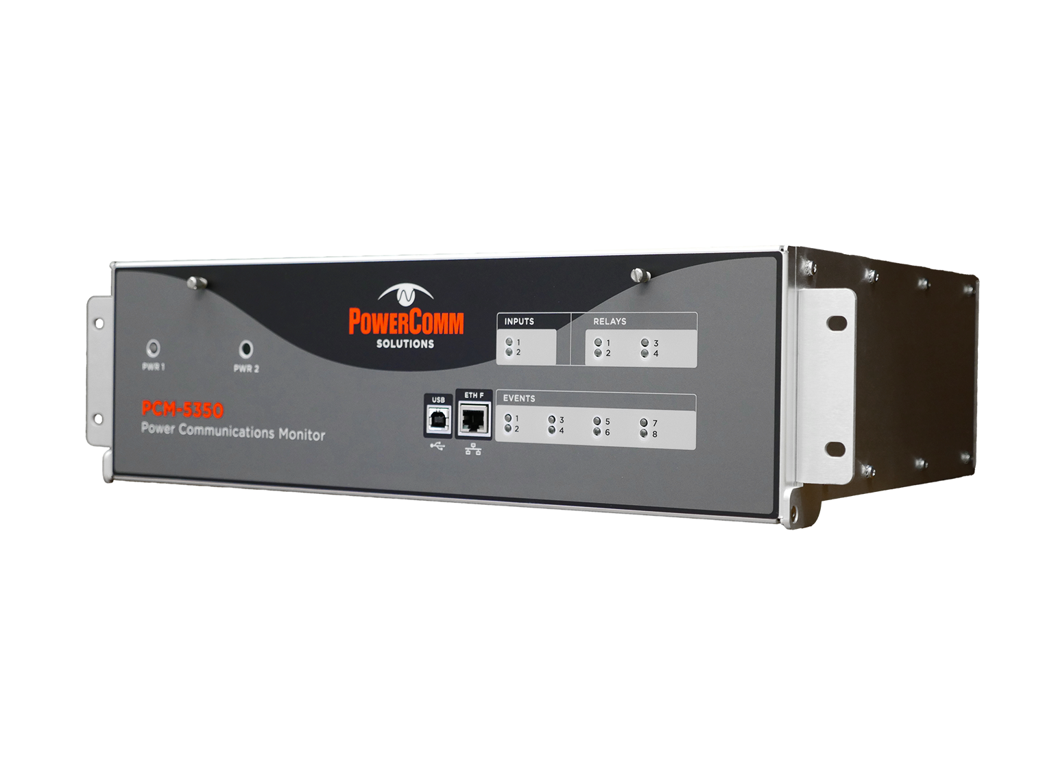
An always-on, five-channel monitor that provides deep, real-time visibility into PLC system performance. Serves as a permanent diagnostic window that identifies and analyzes issues without needing to log into a transmitter-receiver or connect a test instrument.
Channels
5 independent
SOE capacity
32,768 events
Trending
Spectral captures
On‑demand + event‑driven
Always‑On System Visibility
The PCM‑5350 is a five‑channel, frequency‑selective monitor designed for continuous, read‑only observation of Power Line Carrier systems. Installed between the last hybrid and line tuner, it measures at the optimal point in the PLC chain, where reflected power, level, and frequency readings are not distorted by hybrid components. It captures real‑time and event‑driven measurements that help utility professionals diagnose mis‑operations, evaluate system performance, and track gradual channel degradation over time, all without requiring access to transmitters or receivers.
Deep Event Recording & Spectral Capture
Up to 32,768 time‑stamped events with triggers on frequency, level, reflected power, impedance, phase, and noise. Trend level, reflected power, impedance, and phase with programmable intervals. Capture and compare "as‑left" snapshots to extend maintenance cycles and reduce unnecessary truck rolls.
32,768
Event Records
6
Trigger Types
Accurate Measurements Where They Matter
The best location to measure reflected power is at the RF input of the line tuner. When hybrids are between the transmitter and tuner, reflected power readings from the transmitter are distorted. These errors are not linear, so no correction factor can compensate. In one documented case, a broken cable at the tuner read 100% reflected power at the tuner but only 4% at the transmitter behind a resistive hybrid. The PCM‑5350, installed between the last hybrid and line tuner, measures at the point that matters, before hybrid components can distort the readings.
An Independent Diagnostic Window
The PCM‑5350 serves as an independent monitoring device for the RF portion of the PLC system, much like a Digital Fault Recorder (DFR) does for power frequency equipment. It cannot affect existing protection system parameters and is not constrained by the protective settings or timers that limit what a receiver can report. This independence allows the PCM to capture raw measurements with greater sensitivity, providing early detection of problems before they impact the protection scheme.
| RF Inputs | |
|---|---|
| Frequency range | 30 kHz to 500 kHz |
| Frequency accuracy | ±3ppm, ±5ppm max for 10 years |
| Frequency temperature stability | ±1.5ppm |
| Tuning accuracy | 1 Hz |
| Frequency display resolution | 7 digit; 1 Hz |
| Amplitude accuracy | ±0.1 dB |
| Insertion loss | 0.1 dB |
| Bridged Z | 1Ω to 9999Ω |
| Bandwidths | 10 kHz; 1200 Hz (±500); 600 Hz (±250); 360 Hz (±150); 240 Hz (±100); 180 Hz (±75); Wideband (30–600 kHz) |
| Connection type | BNC and UHF |
| Max input | 206 Vrms / 292 Vp; 2.0 Arms max |
| Power Supply | |
| Input voltage | 24, 48, 125, or 250 Vdc |
| Power requirements | 7 Watts |
| Redundancy | Optional |
| Inputs | |
| Type | 2 inputs — optically isolated |
| Voltages | Jumper configurable: 5, 24, 48, 125, or 250 Vdc |
| Outputs & Alarms | |
| Relays | 4 programmable solid state, 125Vdc @ 1A |
| Power fail | 2 Form C, 125Vdc @ 0.5A |
| LEDs | 8 event programmable (red); 4 relay status (red); 2 input status (red); 1 power status (green) |
| IRIG-B Timecode Input | |
| Connector | 1 rear, BNC |
| Signal type | Software programmable for modulated (10Vpp max) or unmodulated (5V TTL) |
| Measurements | |
| Voltage level | dBm and Vrms |
| Current | Arms |
| Power | Watts |
| SWR | Ratio, dB and percent |
| Bridge Z | Ohms |
| Bandwidth | Hz |
| Communication Ports | |
| USB | 1 front, Type B, 12 Mbps (v2.0) |
| Ethernet | 1 front, 1 rear, RJ-45, 10BASE-T / 100BASE-TX |
| RS-422/485 | 1 rear, terminal block, 9600–115200 baud |
| RS-232 | 1 rear, 9-pin D-sub, 9600–115200 baud |
| Environmental | |
| Temperature range | -20°C to +60°C |
| Relative humidity | 95% max, non-condensing @ +40°C |
{{ group.group }}
The PCM‑5350 installs between the last hybrid and line tuner for continuous, read‑only monitoring of your PLC system. Below are its primary use cases.

PCM-5350 system connection diagram
| Description | Part Number |
|---|---|
| Base unit (125 Vdc) | PCM-5350-125 |
| Base unit (48 Vdc) | PCM-5350-48 |
| Base unit (250 Vdc) | PCM-5350-250 |
| Redundant power supply option | PCM-5350-RPS |
| Rack mount kit | RMK-5350 |
Ready to order or need a custom configuration?
Contact our sales team for pricing, lead times, and custom build options.